


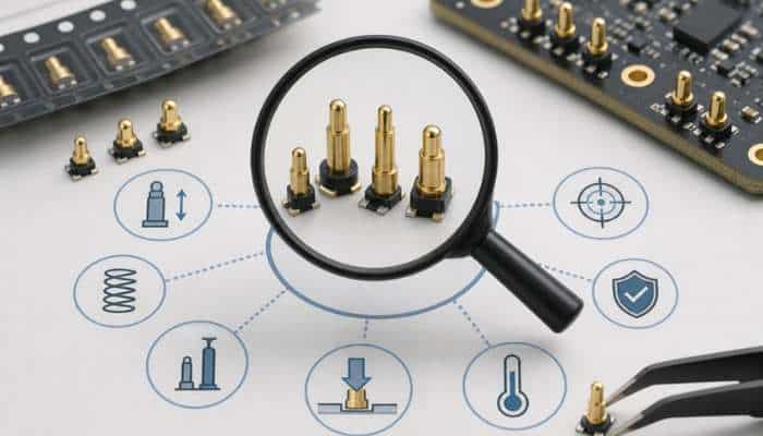

SMT pogo pins are soldered directly onto surface pads on a PCB using standard reflow processes, which means they integrate cleanly into automated assembly lines without requiring a separate through hole soldering step. The spring-loaded contact mechanism allows them to make and break connections repeatedly while maintaining consistent contact force across the full working travel of the pin. Getting the selection right from the start means your final product connects reliably, survives the mechanical demands of its environment, and assembles without complications.
Understanding What SMT Pogo Pins Are Actually Used For
Before getting into the selection criteria, it is worth being clear on the categories of application where SMT pogo pins appear most frequently, because the application context shapes almost every parameter decision that follows.
Charging interfaces are one of the most common uses. True wireless earbuds in their charging cases, smartwatches on their charging cradles, and medical wearables with proprietary charging contacts all use SMT pogo pins because they provide a clean, sealed interface that works without the user having to align a plug. The pin compresses when the device is placed correctly and makes reliable contact without any mechanical coupling that could wear out over time.
Board-to-board connections within a sealed enclosure are another frequent application. When two PCBs need to connect inside a housing that is assembled during manufacture and not intended to be opened regularly, SMT pogo pins on one board pressing against contact pads on the other provide a reliable connection that tolerates small misalignments and dimensional variation in the housing.
Test and programming interfaces on consumer and industrial electronics use SMT pogo pins as the target contacts for bed-of-nails test fixtures and in-circuit programming jigs. The pins on the PCB are compressed by the corresponding contacts in the fixture, allowing electrical testing or firmware programming without any permanent connector that would add cost and occupy board space in the finished product.
Current Rating and Electrical Specifications
The electrical specifications of the pin need to match what the application actually demands, and getting this wrong is one of the more common and more avoidable mistakes in pogo pin selection.
Current rating is the starting point. SMT pogo pins are available in a range from well under one amp for signal and data applications up to several amps for power and charging applications. Selecting a pin rated for significantly more current than the application requires adds unnecessary size and cost. Selecting one that is marginal for the current it will carry creates a reliability risk, particularly at elevated temperatures where contact resistance can increase.
Contact resistance is the companion specification to current rating. Lower contact resistance means less voltage drop across the pin and less heat generated during operation. For signal applications where the electrical signal level is low, contact resistance matters more than for power applications where a few milliohms of additional resistance is negligible. Check the contact resistance specification at the operating current and verify it is appropriate for the signal integrity requirements of your circuit.
Voltage rating is rarely a limiting factor for most consumer and light industrial applications but is worth confirming for anything involving higher voltages or safety-critical isolation requirements.
Physical Dimensions and PCB Footprint
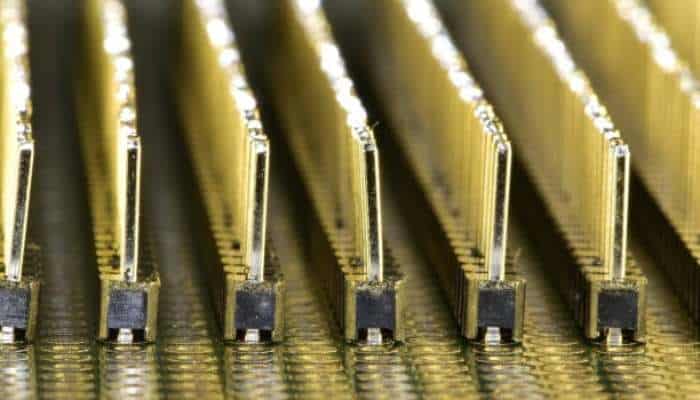
The physical dimensions of an SMT pogo pin determine whether it fits the available board space, achieves the required working travel, and mates correctly with whatever it is contacting on the other side.
Barrel diameter is the primary dimension that affects how much board space the pin occupies. Smaller diameter pins allow tighter spacing in high-density layouts but have lower current ratings and less spring force. Larger diameter pins carry more current and provide more robust mechanical contact but require more board area per pin.
Compressed height and extended height define the working range of the spring mechanism. The difference between these two dimensions is the working travel of the pin. Your design needs to ensure that when the mating surfaces are at their closest tolerance position, the pin is not fully compressed, and when they are at their farthest tolerance position, the pin is still making contact with adequate spring force. Getting this geometry right requires accounting for all the dimensional tolerances in the assembly stack-up.
Pin pitch matters when you are using multiple pins in an array. Standard pitches make it easier to work with pick-and-place equipment and simplify the PCB footprint design. Non-standard pitches are available for applications with specific spacing requirements but may add lead time for custom configurations.
Spring Force and Contact Reliability
Spring force is the parameter that most directly determines contact reliability in service, and it is one that engineers sometimes underspecify because a lower force seems safer for the mating surface.
The spring force needs to be high enough to maintain reliable electrical contact under all conditions the product will experience in service. Vibration, thermal expansion and contraction, and the accumulated mechanical wear of repeated connection cycles all work against contact reliability. A spring force that is adequate under ideal static conditions may not be sufficient when the product is in use in a real environment.
At the same time, spring force that is too high for the mating surface or the surrounding structure creates different problems. Delicate contact pads can be damaged by excessive contact pressure over time. Structural components that are not designed to resist the cumulative force of many pins at high spring force can deform over the product’s service life.
The typical range for SMT pogo pins in consumer applications is between 50 and 200 grams of force per pin. Signal applications tend to use the lower end of this range. Power and charging contacts use the higher end. For applications involving many pins in close proximity, the total cumulative force across all pins is a useful number to calculate and check against the mechanical design of the surrounding structure.
Plating Specification and Surface Compatibility
The plating on the pin tip and barrel determines contact resistance, wear resistance, and corrosion behaviour over time.
Gold plating is the standard for most electronic applications because it maintains low contact resistance without forming oxide layers. Thicker gold plating provides better wear resistance for high-cycle applications such as test contacts and charging interfaces. Nickel underplating beneath the gold layer adds hardness and acts as a diffusion barrier, preventing base metal migration over time.
The mating surface material also influences plating choice. A gold-plated pin contacting a gold pad maintains stable low resistance. Contacting a bare copper or tin-plated surface will produce higher and less stable contact resistance, which is worth accounting for in the circuit design.
Evaluating Suppliers Before You Commit
The quality of SMT pogo pins varies considerably between suppliers, and the differences show up in ways that matter for long-term reliability rather than initial performance.
Dimensional consistency across production batches is one of the most important factors. A pin that measures within specification on a sample but varies outside tolerance in production creates assembly problems and field reliability issues that are expensive to diagnose. Suppliers with ISO certified processes and documented controls are more likely to deliver consistency across real production quantities.
Sample availability before committing to a production order is a reasonable expectation from any credible supplier. Testing actual samples in your application, including spring force, contact resistance, and cycle testing, is the only reliable way to validate that a pin performs to specification in your design rather than just on a datasheet. Lead time consistency and on-time delivery are the final practical checks worth making before placing an order.
Frequently Asked Questions About SMT Pogo Pins
What is the difference between SMT and SMD pogo pins?
The terms are used interchangeably in most contexts. SMT stands for surface mount technology and SMD stands for surface mount device. Both refer to the same category of pogo pin that is soldered onto surface pads on a PCB using a reflow process rather than inserted through drilled holes.
Can SMT pogo pins be used in reflow soldering alongside other components?
Yes, that is one of their main practical advantages. SMT pogo pins are designed to withstand standard reflow soldering temperatures and can be placed and soldered in the same pass as other surface mount components on the board, which keeps the assembly process simple and cost-effective.
How many connection cycles can an SMT pogo pin typically handle?
This depends on the specific product and plating specification, but quality SMT pogo pins are typically rated for anywhere between 10,000 and 100,000 cycles depending on the application. Charging contacts and test interfaces that see frequent use should be specified with higher cycle ratings and heavier gold plating.
What happens if the spring force is too low for my application?
Insufficient spring force leads to intermittent contact, particularly under vibration or thermal cycling. The pin may make electrical contact under ideal static conditions but fail to maintain it when the product is in use. Always verify that the spring force specification provides reliable contact across the full dimensional tolerance range of your assembly.
Do SMT pogo pins require any special PCB pad design?
The pad design needs to match the pin’s footprint dimensions and provide adequate solder area for a reliable joint. Most manufacturers provide recommended PCB footprint data for each pin series. Following the manufacturer’s footprint recommendation rather than improvising your own pad size produces the most consistent solder joint quality in production.
Is it possible to get custom SMT pogo pins if standard sizes do not fit my design?
Yes. Manufacturers with ODM capability can produce custom barrel diameters, lengths, tip geometries, and plating specifications to match an application that standard catalogue options do not cover. This is particularly relevant for compact wearable and medical device designs where the available space envelope is tightly defined.
